Introduction
Before a part ever sees a production floor, you want to know one thing: will it hold up under load? Static stress analysis — the backbone of finite element analysis (FEA) — answers that question. It tells you where stress concentrates, how much a part deflects, and whether your design has a safe margin against failure.
SOLIDWORKS Simulation makes this remarkably accessible. You don’t need a PhD in structural mechanics to get useful first-pass results. This guide walks you through your first static analysis from start to finish.
What Is a Static Stress Analysis?
A static (or linear static) analysis assumes:
- Loads are constant — no vibration, no impact, no changing forces over time
- Material stays elastic — no permanent deformation, the part springs back
- Deformations are small — the shape doesn’t change enough to affect the load path
These assumptions hold true for a huge range of real-world parts: brackets, housings, frames, fixtures, and machine components under normal operating conditions. If your part needs to handle impact, heat, large bending, or repeated cycling, you’ll need one of the more advanced SOLIDWORKS Simulation tiers — but static analysis is where everyone starts.
What You’ll Need
- SOLIDWORKS Simulation Standard (or higher — Professional and Premium also include static analysis)
- A part or assembly open in SOLIDWORKS
If you have SOLIDWORKS Design Premium, you already have Simulation Standard included — you may not need to buy anything extra.
Step 1: Enable the Simulation Add-In
By default, the Simulation tab is hidden. Here’s how to turn it on:
- Go to Tools → Add-Ins (or click the down-arrow next to the gear icon and select Add-Ins).
- In the list, find SOLIDWORKS Simulation.
- Check the box in the Start-Up column so it loads every time you open SOLIDWORKS.
- Click OK.
You’ll now see a Simulation tab in the CommandManager ribbon.
Step 2: Create a New Study
- With your part or assembly open, click the Simulation tab.
- Click New Study.
- In the PropertyManager on the left, select Static and name your study (e.g., “First Analysis”).
- Click the green checkmark.
A new Simulation design tree appears at the bottom-left of your screen. This is your command centre for the analysis.
Step 3: Assign Material
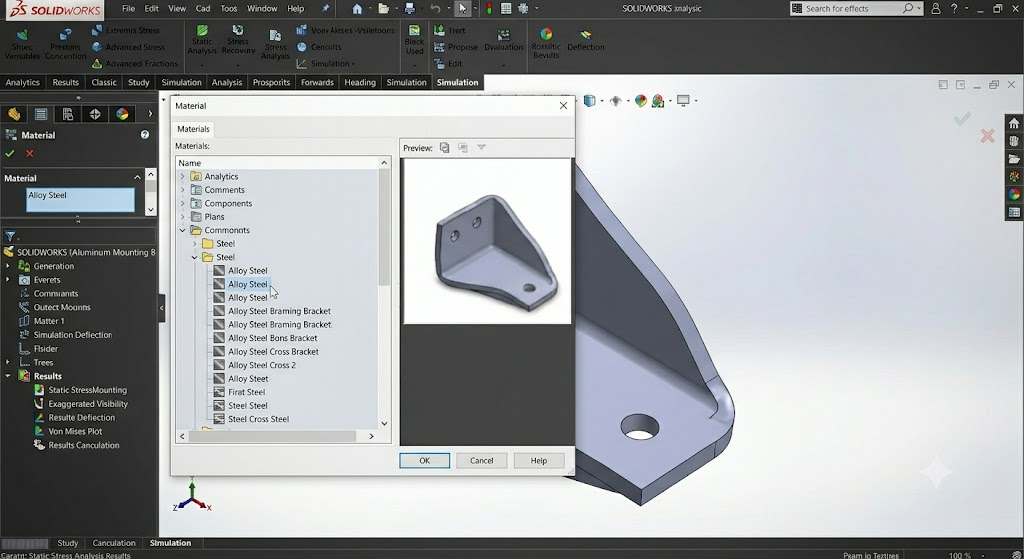
The solver needs to know what your part is made of — elastic modulus, Poisson’s ratio, yield strength, and density all affect the result.
- Right-click Part name under the study tree and select Apply/Edit Material.
- Browse the SOLIDWORKS material library (e.g., Steel → Alloy Steel or Aluminum → 6061 Alloy).
- Click Apply then Close.
Pro tip: If you’ve already assigned a material to the model in the CAD environment, it carries over automatically — you can skip this step.
Step 4: Define Fixtures (How Is It Held?)
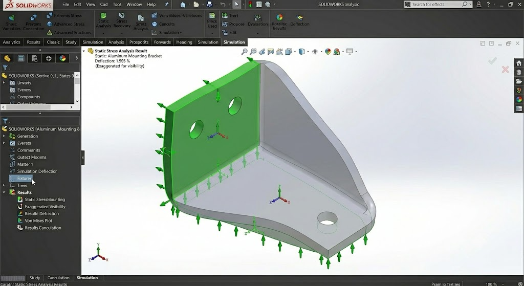
Fixtures represent how the part is constrained in the real world — bolted down, welded, pressed into a slot, etc.
- Right-click Fixtures in the study tree and choose Fixed Geometry.
- Select the faces that are constrained (e.g., the mounting holes or base plate).
- Click the green checkmark.
Common fixture types:
- Fixed Geometry — fully constrains all degrees of freedom (rigid support)
- Roller/Sliding — can slide along a plane but not come off it
- Fixed Hinge — cylindrical faces that can rotate but not translate
Step 5: Apply Loads
Now tell the solver what’s pushing on your part.
- Right-click External Loads in the study tree and choose Force (or Pressure, Torque, etc.).
- Select the face, edge, or vertex where the load is applied.
- Enter the force value (e.g., 500 N) and direction.
- Click the green checkmark.
You can apply multiple loads and even split them across different faces — for example, a 1000 N downward force on the top face and a 200 N side load from a cable pull.
Step 6: Mesh the Model
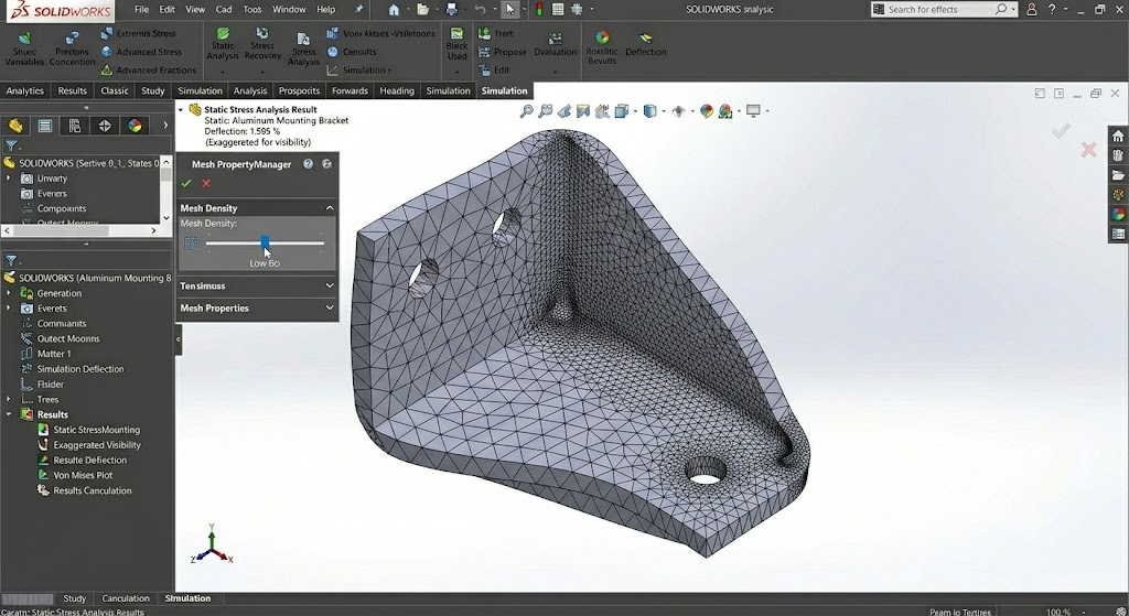
FEA works by dividing your geometry into small elements (tetrahedrons, by default). This collection of elements is the mesh.
- Right-click Mesh in the study tree and choose Create Mesh.
- Use the default settings for a first run (the slider controls coarseness vs. fineness).
- Click the green checkmark.
For a first analysis, the default solid mesh is usually adequate. A finer mesh gives more accurate results but takes longer to solve. A good practice: run once with the default mesh, then refine areas of high stress and re-run to check convergence.
Step 7: Run the Analysis
- Click Run This Study in the Simulation tab, or right-click the study name and select Run.
- A progress bar shows the solver at work. Depending on model complexity and mesh density, this could take seconds or minutes.
- When it finishes, SOLIDWORKS automatically generates result plots.
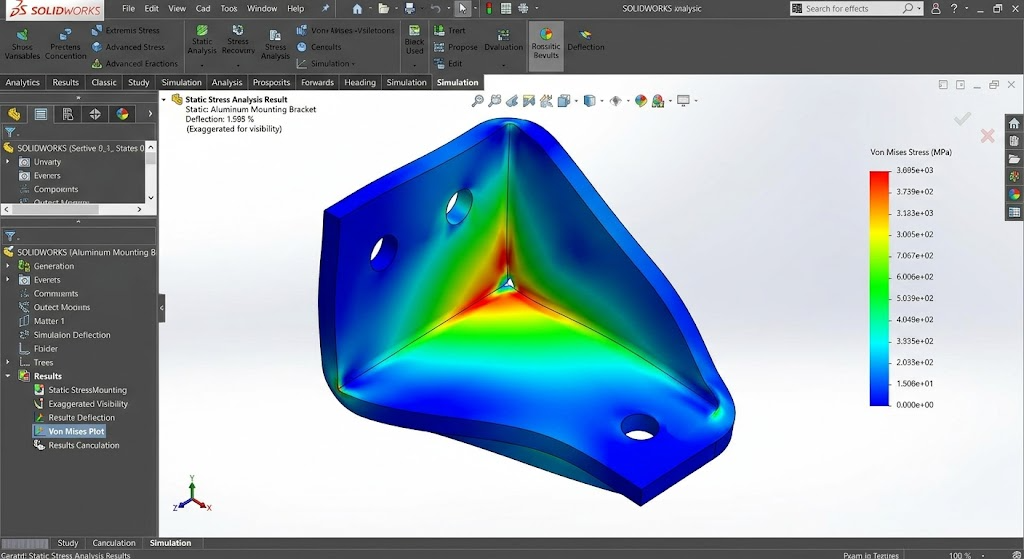
Step 8: Interpret the Results
Three default plots appear — these are the most important ones to understand:
1. Stress (von Mises)
Shows the equivalent stress across the part. The colour bar ranges from blue (low stress) to red (high stress). Compare the maximum stress to your material’s yield strength — if red zones exceed yield, the part will permanently deform.
2. Displacement (URES)
Shows how much each point moves. This is useful for checking deflection limits — for example, a bracket might hold stress-wise but deflect more than the assembly tolerance allows.
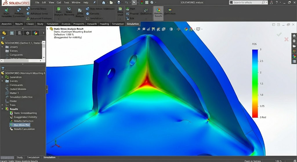
3. Factor of Safety (FOS)
SOLIDWORKS can plot a factor of safety distribution. FOS = Yield Strength ÷ Actual Stress. A value of:
- < 1 → The part fails at that location
- 1 – 2 → Marginal; acceptable only with high confidence in loads and material
- 2 – 3 → Typical target for general engineering
- > 3 → Over-designed (opportunity to lighten / reduce material)
Tips for Your First Analysis
- Start simple — analyse a single part before moving to assemblies with contacts and connectors.
- Use the default mesh first — get a feel for results before refining.
- Check units — make sure forces and dimensions are consistent (N/mm/SI vs IPS).
- Right-click your results — you can list result details (exact max/min values) and create section or iso clipping plots to see internal stress.
- Save different iterations — use the Trend Tracker to compare design changes side by side.
Which Simulation Tier Do You Need?
| Tier | Static Analysis | Also Includes |
|---|---|---|
| Standard | ✓ Yes | Fatigue, event-based motion, Trend Tracker |
| Professional | ✓ Yes | Frequency, buckling, thermal, drop test, topology optimisation |
| Premium | ✓ Yes | Nonlinear, composites, advanced dynamics |
All three tiers share the same workflow and user interface, so the steps in this guide apply no matter which license you have.
Final Thoughts
Running your first static stress analysis is a milestone — it moves you from guessing to knowing. The process is intuitive: material → fixtures → loads → mesh → run → review. Once you’ve done it once, the workflow becomes muscle memory, and you’ll find yourself reaching for Simulation earlier and earlier in the design process.
The real value? Fewer prototypes, shorter iterations, and the confidence that the part you’re sending to manufacturing has already been tested on your screen.
Need help choosing the right Simulation tier for your team, or looking for training to level up your FEA skills? Get in touch — we’re here to help.